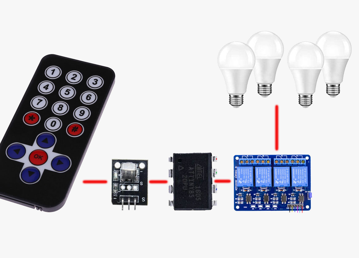
Welcome! Today we are going to build an Infrared Remote Control Switch using ATTiny85 Microcontroller. If you can recall, we have built an infrared switch before using CD4017 integrated circuit. If you built the previous Infrared remote control switch using CD4017 you will notice a very common disadvantage with the circuit. With the previous infra-red remote control switch we built, aiming any type of IR remote controller to the device and pressing about any key just triggers the system either OFF or ON. This isn’t desirable; imagine you used the device to control your room light, any time you try to change the channel on you television it may also turn off the room light. Also you can’t control multiple devices with the system. This is so because the previous infra-red circuit have no way to differentiate the key that was pressed on the remote controller. So it just treats every IR signal as one.
But today, we are going to build a better Infrared remote controller switch using ATTiny85 microcontroller unit that will be smarter enough to determine what keys you have pressed on the IR remote transmitter and act accordingly to switch different loads or appliances ON or OFF. This means, the system will not respond to every type of signal from the IR remote controller but only to the ones it have been programmed to respond to.
The Infrared Remote Control Switch is very simple because it uses few components which you can find in any electronics parts or hobbyist shop around you.
The heart of the system is the popular ATTiny85 MCU. So we will be using Arduino IDE to program it. In addition to the Arduino IDE, you also need a hardware programmer to actually send the Arduino Sketch(Code) into the ATTiny85. There are different types of AVR programmers in the market that can be used to program the ATTiny85 microcontroller but if you don’t have any of the dedicated AVR programmers, you can use an Arduino board as an ISP programmer. This tutorial “How to use Arduino Uno as AVR programmer” explains how to convert an Arduino board into an ISP programmer which is the method am going to be using here to program the ATTiny85 microcontroller.
So, I will assume you have configured an Arduino board to be used as an ISP programmer. Then connect the Arduino ISP programmer to the ATTiny85 as illustrated in the diagram below.
Arduino ISP connection with ATTiny85
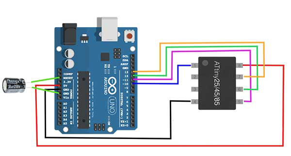
Now download the Arduino sketch provided in the “The Sketch / Code” section below and burn it into the Microcontroller. You may want to look at my post on how to burn a sketch into a microcontroller.
The Sketch / Code
Hardware Components List
| ATTiny85 x1 | Buy here |
| IR Remote Control Kit x1 | Buy here |
| 4 channels, 5v relay module | Buy here |
| Arduino Development Board x1 | Buy here |
| C1 – 10uf/16v electrolytic capacitor | Buy here |
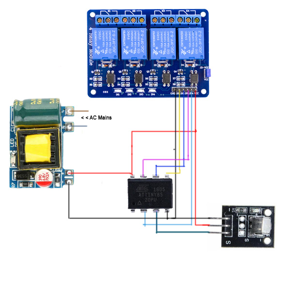
Schematic Diagram
IR remote controller and the corresponding button HEX codes

| Key | HEX | Key | HEX |
| 1 | 0xFFA25D | 0 | 0xFF9867 |
| 2 | 0xFF629D | * | 0xFF6897 |
| 3 | 0xFFE21D | # | 0xFFB04F |
| 4 | 0xFF22DD | Up | 0xFF18E7 |
| 5 | 0xFF02FD | Down | 0xFF4AB5 |
| 6 | 0xFFC23D | Left | 0xFF10EF |
| 7 | 0xFFE01F | Right | 0xFF5AA5 |
| 8 | 0xFFA857 | Ok | 0xFF38C7 |
| 9 | 0xFF906F | Repeat key | 0xFFFFFF |
How the Infrared Remote Control Switch works
The remote controller unit is based on the NEC protocol, so it transmits within 38 kHz. Pointing the IR controller to the IR receiver module, and pressing any key sends a unique 38 KHz code to the IR receiver module which is processed by the ATTiny85.
The code is converted to HEX and compared with the known HEX codes of the keys 1, 2, 3 and 4 of the remote controller to determine which relay to energize or de-energize. A 5v/4 channels relay module, acting as four SPST switches, is used to control 4 different devices upon pressing switch 1 through 4 on the remote controller.
Application of the Infrared Remote-Control Switch
The Infrared Remote-Control Switch can be used to control (switch ON/OFF) electronic appliances or devices (bulb, Fan, etc.) using any of the infrared remote controller that is based on the NEC protocol.
You can share the tutorial with your friends using the social media buttons and if you have built the circuit or have any question, tell us through the comment box below. Thanks for reading.







One thought on “Infrared Remote Control Switch using ATTiny85”
I need a content like this on the topic of intruder alert system using IOT