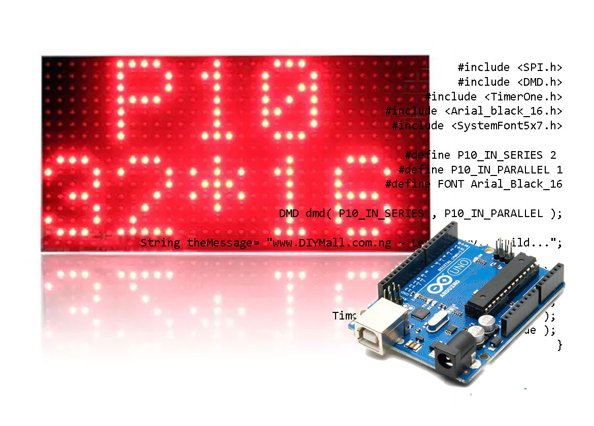
Electronics Message Display, Electronics Bill Board or Dot-Matrix Display are all name for the same thing – an electronics system that displays (normally in a scrolling) message or information. Electronics message displays are seen everywhere – from supermarkets, patrol station or restaurants. In this tutorial, I will teach you how to build your own message display using an Arduino Uno and P10 DMD Module.
Motivation for project
Recently, a customer ordered P10 module from our shop. Unfortunately, he mistook the P10 to be an Electronics Message Display. When he called me, asking how he is going to enter information into the P10 board and power it. He explained that he owns a school and wants to use his new acquisition for displaying information in the school. I knew he is mistaking. I explained to him and ask him to return the P10 for a refund since he isn’t into electronics so I think the P10 is useless for him. Then I thought, why not build him a complete message display using Arduino and the P10. This is what we will be building today.
Components Needed for the Electronics Message Display
| Arduino UNO x1 | Buy here |
| P10 Dot Matrix Display Module SMD (Red) x 2 | Buy here |
| 5v 6A Power supply x 1 | Buy here |
| Connection Wires | Buy here |
The Schematic Diagram

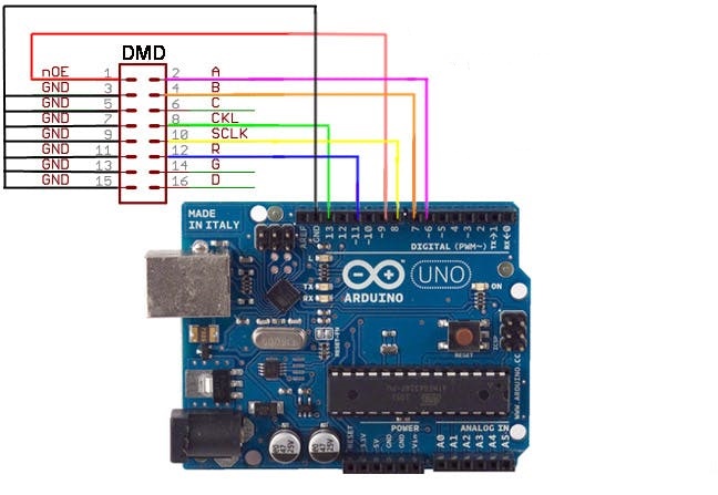
The Arduino Uno is the heart of the system. So first we connect the P10 Module to the Arduino Uno. The P10 DMD Module has 32*16 LEDs matrices. That means, there are 32 LEDs in each row and 16 LEDs in each column. So there is a total of 512 LEDs in each of the modules.
In our project we will be using two P10 Modules connected in series, so we will have a total matrix of 64×16 (1024 LEDs). Each of the P10 Module comes with two sets of 16 Pin FRC connector and a power connector. One of the FRC connectors (the input) will be interfaced with Arduino and the other is for extension to other P10 module.
| P10 Module | Arduino Uno |
| OE | Digital pin 9 |
| A | Digital pin 6 |
| B | Digital pin 7 |
| CLK | Digital pin 13 |
| LAT | Digital pin 8 |
| DR | Digital pin 11 |
| GND | GND |
Power Supply Module
You can power the system with any 3-5A, 5V power supply. If you plan to add more modules in the future, you can buy this 10A 5v power supply.
The sketch (Code)
/*>>>>>>>>>>>>>>>>>>>>>>>>>>>>>>>>>>>>>>>>>>>>>>>>>>>>>>>>>>>>>>>>>>>>>>>>>>>>>>>>>>>>>>>>>>>>>>>>>>>>>>>>>>>>>
Project: Electronics Message Display using Arduino Uno and P10 DMD Module
Copyright (C) 2021 Obiako Izuchukwu,
For: www.DIYMall.com.ng
>>>>>>>>>>>>>>>>>>>>>>>>>>>>>>>>>>>>>>>>>>>>>>>>>>>>>>>>>>>>>>>>>>>>>>>>>>>>>>>>>>>>>>>>>>>>>>>>>>>>>>>>>>>>>>*/
#include <SPI.h>
#include <DMD.h>
#include <TimerOne.h>
#include <Arial_black_16.h>
#include <SystemFont5x7.h>

#define P10_IN_SERIES 2
#define P10_IN_PARALLEL 1
#define FONT Arial_Black_16

DMD dmd( P10_IN_SERIES , P10_IN_PARALLEL );

String theMessage= "www.DIYMall.com.ng ~ Learn. Buy.. Build...";

void setup() {
  Serial.begin(9600);
  Timer1.initialize( 2000 );
  Timer1.attachInterrupt( ScanP10 );
  dmd.clearScreen( true );
}

void loop(){
  Serial.println(theMessage);
  displayMessage(theMessage);
}

void ScanP10(){
  dmd.scanDisplayBySPI();
}

void displayMessage( String message ){
  long start = millis();
  long timer = start;
  boolean done = false;
   char newString[512];
   int sLength = message.length();

  dmd.clearScreen( true );
  dmd.selectFont( FONT );

  message.toCharArray( newString, sLength + 1 );
  dmd.drawMarquee( newString , sLength , ( 32*P10_IN_SERIES )-1 ,0);

  while( !done ) {
    if ( ( timer + 20 ) < millis() )  {
      done = dmd.stepMarquee( -1 , 0 );
      timer = millis();
    }
  }
}
Note: check below in the “Download” section for links to libraries you need for this project.
The sketch is pretty straight forward. First we included the libraries and Fonts that we want to use in the program.
Then, we declared constants to hold the number of P10 modules we connected in series and in parallel. Then we declared our font style and initialized the DMD.
In the setup method, we set and begin the serial communication, initialized a timer, setup an interrupt on the timer to call a function ScanP10(), then we cleared the screen, so nothing will be shown initially.
In the loop, we printed content of “theMessage” variable to the serial output and then called displayMessage(“”) method and pass it the “theMessage” variable.
After here, the next is the two methods we have called ealier. scanP10() method checks periodically to see if there’s any information from the Arduino side to the P10 Module and if there is, it triggers the interrupt.
displayMessage() method, as the name suggests, is actually the method that displays the message on the Dot Matrixes LED array from left to right, giving the scrolling impression.
Application of the System Electronics Message display using Arduino Uno and P10 DMD
This system can be used in different places for either advertising, as a notice / information board of just for decoration.
Watch it work
Downloads:
Download Sketch
Download DMD Library
Download TomerOne Library

